S-N Fatigue Properties
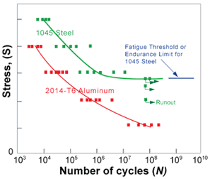
 There are two general types of fatigue tests conducted. One test focuses on the nominal stress required to cause a fatigue failure in some number of cycles. This test results in data presented as a plot of stress (S) against the number of cycles to failure (N), which is known as an S-N curve. A log scale is almost always used for N.
The data is obtained by cycling smooth or notched specimens until failure. The usual procedure is to test the first specimen at a high peak stress where failure is expected in a fairly short number of cycles. The test stress is decreased for each succeeding specimen until one or two specimens do not fail in the specified numbers of cycles, which is usually at least 107 cycles. The highest stress at which a runout (non-failure) occurs is taken as the fatigue threshold. Not all materials have a fatigue threshold (most nonferrous metallic alloys do not) and for these materials the test is usually terminated after about 108 or 5x10⁸ cycles.
Since the amplitude of the cyclic loading has a major effect on the fatigue performance, the S-N relationship is determined for one specific loading amplitude. The amplitude is express as the R ratio value, which is the minimum peak stress divided by the maximum peak stress. (R=σmin/σmax). It is most common to test at an R ratio of 0.1 but families of curves, with each curve at a different R ratio, are often developed.
A variation to the cyclic stress controlled fatigue test is the cyclic strain controlled test. In this test, the strain amplitude is held constant during cycling. Strain controlled cyclic loading is more representative of the loading found in thermal cycling, where a component expands and contracts in response to fluctuations in the operating temperature.
It should be noted that there are several short comings of S-N fatigue data. First, the conditions of the test specimens do not always represent actual service conditions. For example, components with surface conditions, such as pitting from corrosion, which differs from the condition of the test specimens will have significantly different fatigue performance. Furthermore, there is often a considerable amount of scatter in fatigue data even when carefully machined standard specimens out of the same lot of material are used. Since there is considerable scatter in the data, a reduction factor is often applied to the S-N curves to provide conservative values for the design of components.