Radiated Fields of Ultrasonic Transducers
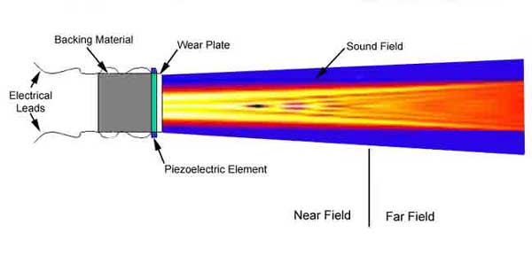
The sound that emanates from a piezoelectric transducer does not originate from a point, but instead originates from most of the surface of the piezoelectric element. Round transducers are often referred to as piston source transducers because the sound field resembles a cylindrical mass in front of the transducer. The sound field from a typical piezoelectric transducer is shown below. The intensity of the sound is indicated by color, with lighter colors indicating higher intensity.

Since the ultrasound originates from a number of points along the transducer face, the ultrasound intensity along the beam is affected by constructive and destructive wave interference as discussed in a previous page on wave interference. These are sometimes also referred to as diffraction effects. This wave interference leads to extensive fluctuations in the sound intensity near the source and is known as the near field. Because of acoustic variations within a near field, it can be extremely difficult to accurately evaluate flaws in materials when they are positioned within this area.
The pressure waves combine to form a relatively uniform front at the end of the near field. The area beyond the near field where the ultrasonic beam is more uniform is called the far field. In the far field, the beam spreads out in a pattern originating from the center of the transducer. The transition between the near field and the far field occurs at a distance, N, and is sometimes referred to as the "natural focus" of a flat (or unfocused) transducer. The near/far field distance, N, is significant because amplitude variations that characterize the near field change to a smoothly declining amplitude at this point. The area just beyond the near field is where the sound wave is well behaved and at its maximum strength. Therefore, optimal detection results will be obtained when flaws occur in this area.

For a piston source transducer of radius (a), frequency (f), and velocity (V) in a liquid or solid medium, the applet below allows the calculation of the near/far field transition point. In the Java applet below, the radius (a) and the near field/far field distance can be in metric or English units (e.g. mm or inch), the frequency (f) is in MHz and the sound velocity (V) is in metric or English length units per second (e.g. mm/sec or inch/sec). Just make sure the length units used are consistent in the calculation.
Spherical or cylindrical focusing changes the structure of a transducer field by "pulling" the N point nearer the transducer. It is also important to note that the driving excitation normally used in NDT applications are either spike or rectangular pulsars, not a single frequency. This can significantly alter the performance of a transducer. Nonetheless, the supporting analysis is widely used because it represents a reasonable approximation and a good starting point.